Description
Chapter 1 Product Introduction
- Common Cathode with Energy-Saving
Common cathode is an energy-saving power supply technology for LED display, which can effectively solve the problems of high screen temperature and excessive power consumption of common anode circuit. the average temperature of the panel of the common cathode circuit is 15℃ lower than that of the traditional common anode circuit,and the power consumption is reduced by more than 20%.
- Quick assembly and disassembly, convenient and efficient
Hidden handles, hard connections, concealed wire design, easy maintenance; fast lock connections on the side for quick assembly and disassembly, high flatness, slim cabinet, lightweight, convenient for transportation, saving time and labor costs. - Collision-resistant design, safe and reliable
High-quality collision-resistant top protection and soft masks are used, with good toughness and impact resistance, effectively protecting LED chips and enhancing the safety of athletes.
- Exceptional picture quality, excellent visual experience
Screen brightness exceeding 5500 nits, clear visibility even in strong light; high refresh rate, high contrast, stable high-definition live images without ghosting, flickering, or ripples.
- High protection level
The cabinet is designed with full waterproof aluminum, featuring corrosion resistance, high precision, good flatness, deformation resistance, and good heat dissipation. Three-in-one outdoor waterproof SMD LED chips, combined with advanced gel-filling technology, can achieve an IP66 protection level, with strong environmental adaptability for all-weather outdoor operation. - Drive solution
It has top and bottom line concealment functions, high refresh rate, first-line dimming improvement, low grayscale color shift, and mura improvement functions.
Chapter 2 Structural Appearance
2.1 Module Pictures
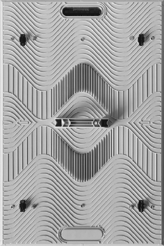
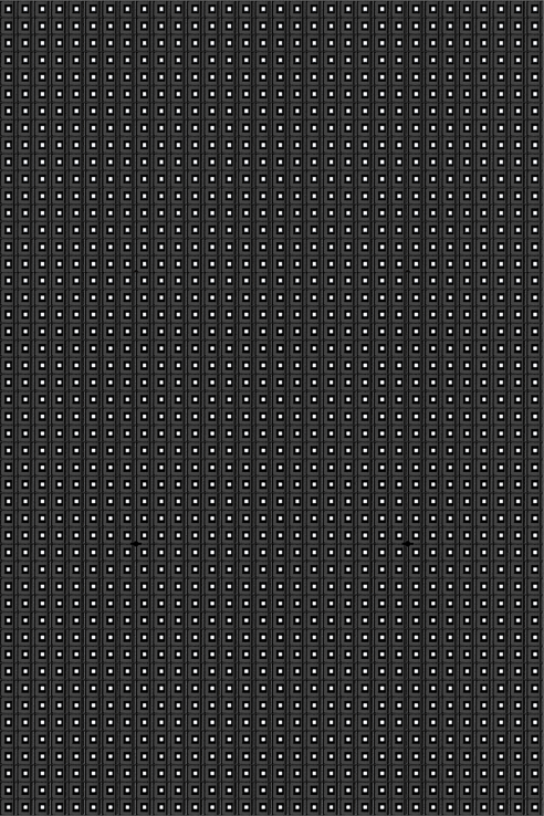
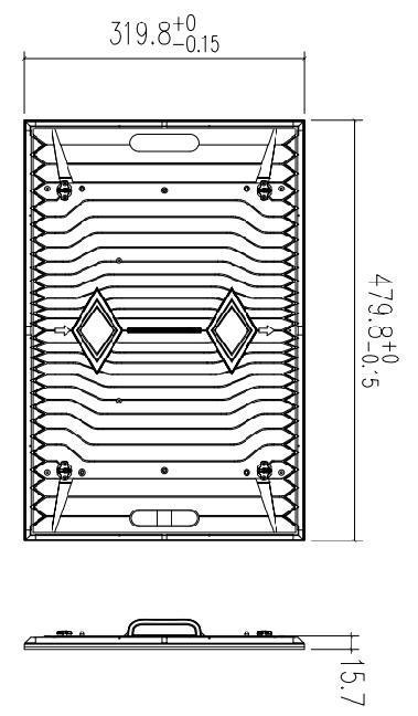
Die-cast aluminium modules(480*320*15.7mm)
2.2 Cabinet Pictures
Die-cast aluminium cabinet(960*960*87mm)
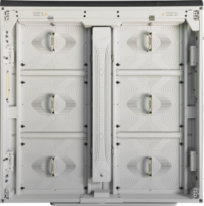
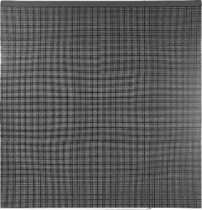
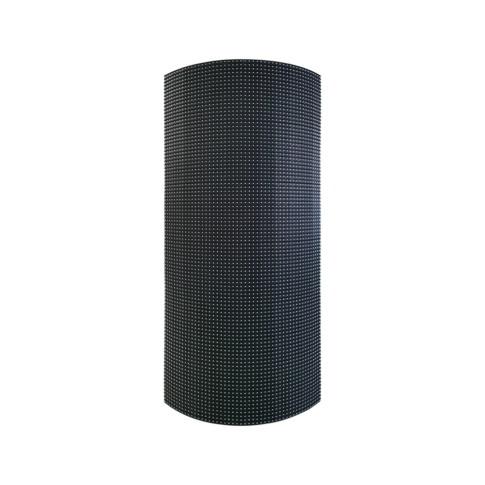
Corner
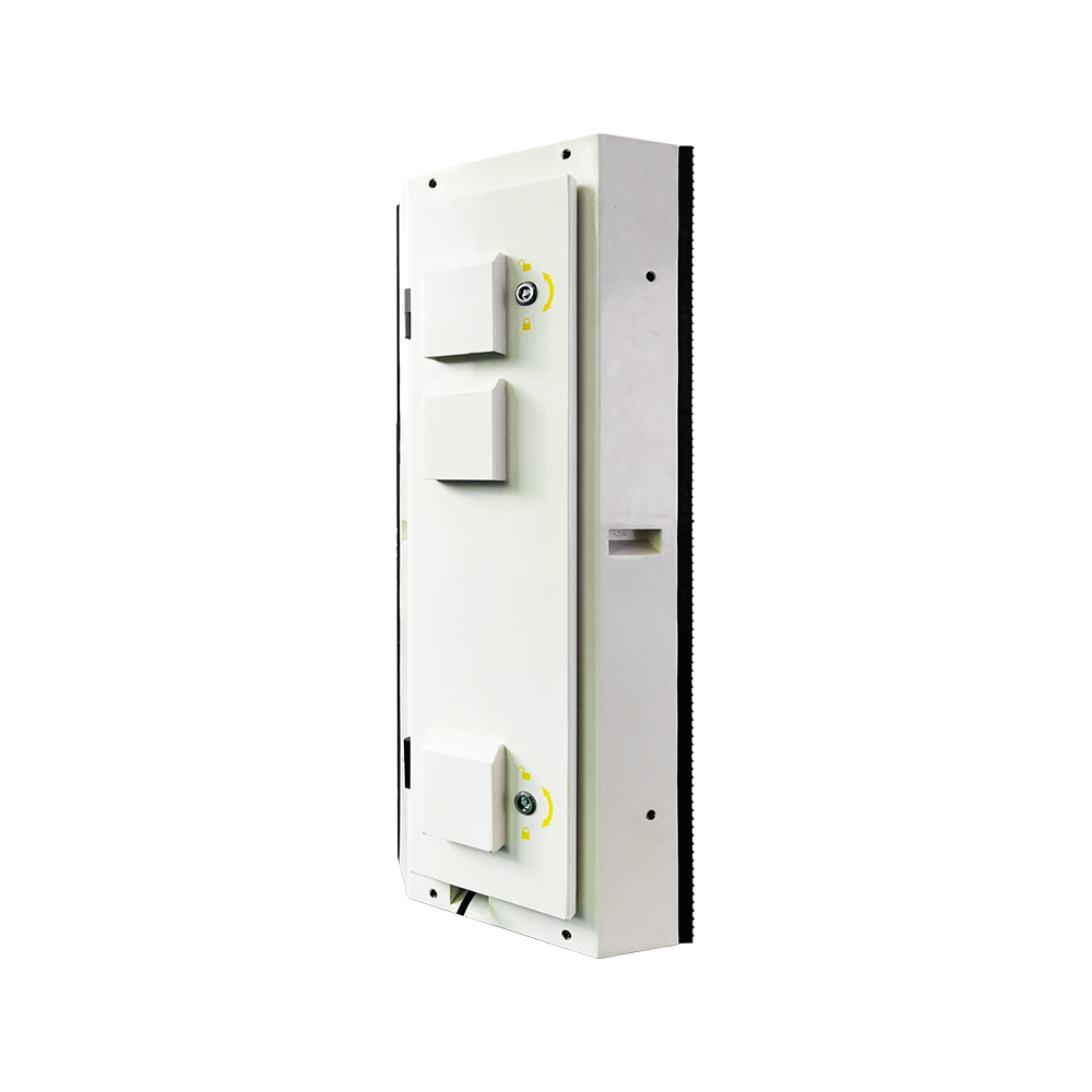
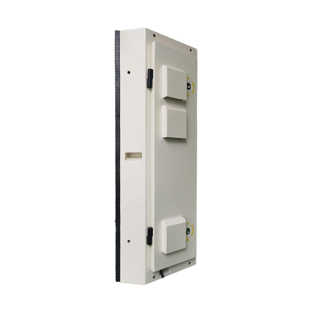 2.3 Technical Parameters
Technical Parameters(Common anode)
*Note: Maximum power consumption fluctuates by 10% depending on the batch of LED chips, and specifications are subject to change without notice.
2.4 Packing List
- Packing List
| Packing List | Quantity | Unit |
| LED Display | 1 | Set |
| User Manual | 1 | pcs |
| Approved Certificate | 1 | pcs |
| Warranty Card | 1 | pcs |
| Construction Notification | 1 | pcs |
2.5 Power Supply Configuration Project
- Supply Configuration Project
| Power Supply | Configuration Project |
| 300/400W Power Supply | Can load 4pcs modules |
2.6 Accessories
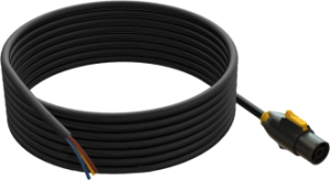
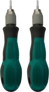
- Accessories List
| Accessories | ||
 |
 |
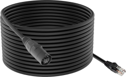 |
| Power Supply | Single Cable | Screws, connecting sheet,
Sleeve Piece |
 |
||
| equipment for front and rear maintenance | ||
Chapter 3 Interface Definition
3.1 Interface Picture(HUB75)
Interface Picture(HUB75)
3.2 Interface Definition
Interface Definition
| Pin | Signal | Function | Pin | Signal | Function |
| 1 | R1 | Red Data Signal | 2 | G1 | Green Data Signal |
| 3 | B1 | Blue Data Signal | 4 | GND | Power Ground |
| 5 | R2 | Red Data Signal | 6 | G2 | Green Data Signal |
| 7 | B2 | Blue Data Signal | 8 | E | Row Decoding Signal |
| 9 | A | Row Decoding Signal | 10 | B | Row Decoding Signal |
| 11 | C | Row Decoding Signal | 12 | D | Row Decoding Signal |
| 13 | CLK | Clock Signal | 14 | LAT | Latch Signal |
| 15 | OE | Enable Signal | 16 | GND | Power Ground |
Chapter 4 Installation
4.1 Kit Installation
Hole Installation Diagram for Kit
4.2 Cabinet Installation
Hole Installation Diagram for Kit

4.3 Display Installation
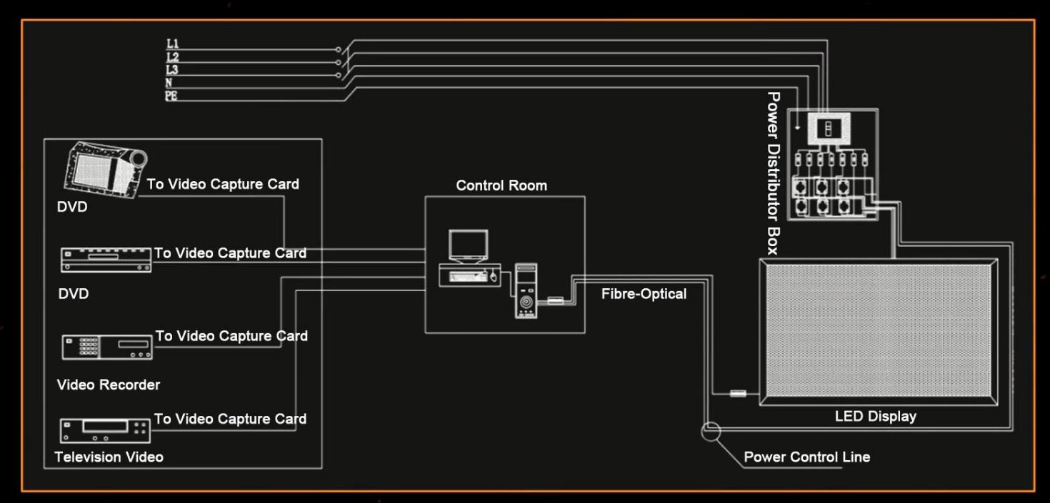
Diagram for Connection
4.4 Networking Introduction
Topographic Picture for networking
Chapter 5 User Manual
5.1 Notification
Notification
| Item | Notification |
| Temperature | Keep the work temperature within -10℃~50℃ |
| Humidity | Keep the storage temperature within -20℃~60℃ |
| Waterproof | Keep the work humidity within 10%RH~98%RH |
| Dust-proof | Keep the storage humidity within 10%RH~98%RH |
| Anti-Electromagnetic radiation | IP66 |
| Electrostatic Prevention | IP66 |
| Temperature | LED display shouldn’t put under the environment where has strong interference by electromagnetic radiation, which would be easy to picture display abnormal. |
| Humidity | It should be ground connected well for power supply, cabinet, mental cover of display body, the resistance of ground connection<10Ω, to avoid making any damage to electric components. |
5.2 User Manual
User Manual
| Item | User Manual |
| Electrostatic Protection | The installer need wear electrostatic ring and electric gloves, each equipment should take ground connection well when installing. |
| Connection Type | There are positive and negative electrode silk printed on module, don’t allow to reverse connect, and prohibit to connect with AC 220V. |
| Operate Type | Prohibit to assemble module, cabinet and whole of display under power on, operation should be under power off completely, to protect personal safety; Prohibit anyone to touch when the LED display is working, in case the static electricity which is generated by body to break through LED and other components. |
| Dismantle and Transportation | Don’t allow to throw, push, compress module, to prevent module falling down, to avoid breaking kit, damage LED chips, etc. |
| Environmental Inspection | It should match temperature and humidity meter for LED display at installation site, to monitor its surrounding environment, so that it can find out if LED display being affected with damp, moisture, etc. |
| The Usage of LED display | 1.The environmental humidity should be 10%RH~65%RH, it is suggested to turn on LED display one time each day, normal to use above 4 hours each time, to remove its damp. |
| 2.When the environmental humidity is above 65%RH, it should make dehumidification to environment, and it is suggested to work LED display above 8h each day. | |
| 3.When LED display has not turned on for a long time, it should preheat LED display to remove moisture before use, to avoid damage LED because of damp, the specific method: 20% brightness to work for 2h, 40% brightness to work for 2h, 60% brightness to work for 2h, 80% brightness to work for 2h, 100% brightness to work for 2h, by this to gradually increase its brightness. |
5.3 Acceptance Request and Method
Acceptance Request and Method for LED display
| Item | Acceptance Request and Method |
| Brightness of LED Display | Switch LED display to work as full brightness, use light-gun to measure the brightness of LED display within 10 minutes. When measuring its brightness, the light-gun need be vertical to LED display, to adjust the distance of light-gun and LED display, ensure the view window, black area, cover above 16 pixels, adjust focal length, to ensure LED chip being able to clearly view in eyepiece, then measure and record brightness data. |
| Visual Angle | The one should stand on the angle of 140°, bottom angle 65°to LED display when making measurement, it is requested that LED display should not have obvious the problem of dark block. |
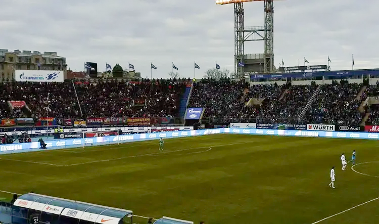
Chapter 6 Application Field

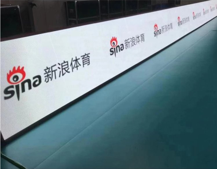





Reviews
There are no reviews yet.